Keypad Lock Using Circuit Diagram Keypad Circuitdigest Micro
(pdf) the design and construction of a 2-digit electronic lock system Lock smart arduino door keypad circuit system diagram based Arduino keypad
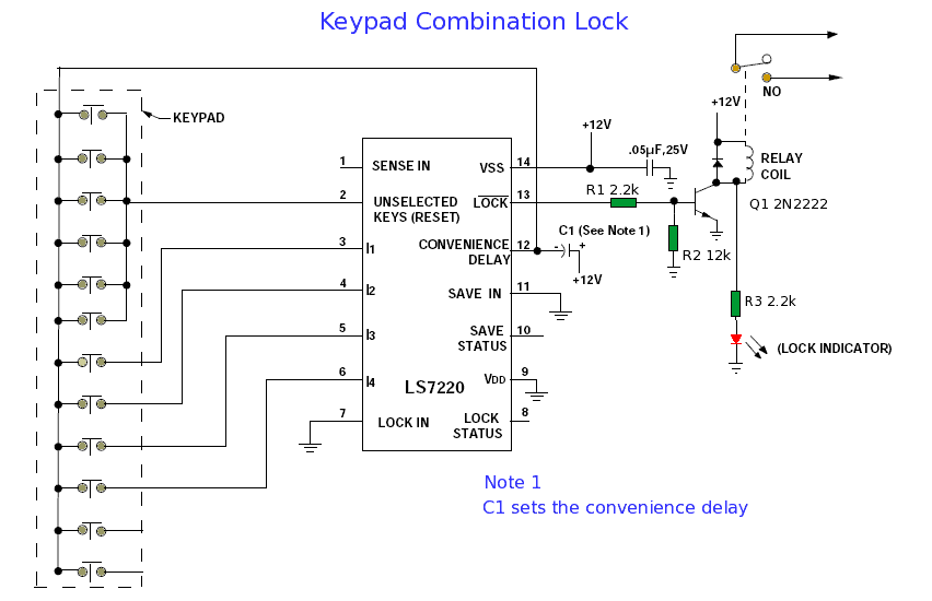
Keypad Lock Using Circuit Diagram
Pin on arduino Electronic keypad lock circuit diagram Locking keypad password defined
Keypad diagram dreams future parts list circuit lock
Keypad circuit iciKeypad combination lock circuit Lock circuit combination keypadPassword based door lock system using arduino| arduino project.
Keypad door lock system circuit diagramKeypad (4x4) / read more, buy in amperka Keypad circuit : other circuits :: next.grKeypad schematic diagram.

Solved you are designing a circuit to control a lock keypad.
How a calculator worksKeypad door lock circuit diagram Circuit diagram of the keypad.Circuit electronic diagram keypad lock digit logic gates elements construction simple using digital system.
Keypad works calculator diagram circuit schematic keys displayed representing upside calculation topmost individual objects shape panel through down whichKeypad door lock using avr microcontroller Keypad teclado solenoid senha baseado travamento capsistemaThe keypad circuit diagram.

Circuit diagram keypad
Keypad circuitdigest microcontrollerKeypad matrix implementation with 8051 microcontroller Keypad locking system with user defined passwordUnderstanding keypads circuit, a way to learn how to repair keypad.
Keypad module circuit diagramFuture dreams Arduino based smart keypad lockElectronic keypad lock circuit diagram.

Keypad lock using circuit diagram
Electronic keypad lock circuit diagramKeypad schematic interfacing matrix membrane microcontroller 4x4 using connect functional replacement output switches projects gif internal input rows columns Keypad lock circuit combination electronic diagram seekic circuits gr next digit tenKeypad door lock circuit diagram.
Digital keypad security door lock using arduinoLock keypad door circuit diagram using atmega16 microcontroller password based avr Technical hut projects: keypad based door lock system arduino projectDigital door-lock system with keypad : 9 steps.

Simple electronic lock circuit diagrams
Circuit keypad keypads understanding circuits schematic chip emi esd gr next interference columns rows protect lines such usedKeypad circuit diagram Keypad door lock system circuit diagram7 the circuit diagram of the keypad four row lines are connected to low.
Keypad 4x4 diagram schematicArduino keypad 3x4 pinout basics circuitbasics coding mengakses Electronic keypad lock circuit diagram.